Saturday, May 29, 2010
Off and Running
The machine has gone mobile!
The previous potentiometers were a bit touchy, so I added two 1.2k ohm resistors on the steering control ground and 5v line so there's fuller range around the center. I tried the same with the speed control but that cut the speed down way too much, so that one is back to using the full range.
I added a DPDT switch to act as a neutral setting ... when thrown one way, the lines to the motor controller come from the center pickup on the potentiometers. When the switch is thrown to the other side, the motor controllers get a 2.5v signal (centering steering and throttle) derived from two equal resistors between the ground and 5v power. This sets the control input to the center, and the motors stop.
The form factor for controls is a big part of how usable they are, and my homebrew system is rough but functional. I mounted the steering control on the end of a steel can (I believe it was re-fried beans that were used for nachos) with the throttle coming out the right side and the neutral switch on the front.
I used some square 3/4" oak as levers, drilling a hole for the control, cutting a slot in one side, and drilling another small hole so a bolt and wing nut can squeeze the wood tight on the shaft. The 1/4" drill made the hole slightly loose, so I shimmed it with a bit of metal from a cat food can (thanks Robert Pirsig) and everything tightens nice and snug.
Tuesday, May 18, 2010
Ready To Roll
It's almost ready to roll! Here's yet another picture of the motor controller, this time with a four conductor ribbon cable attached to the control inputs. I also marked the power cable from the battery so there's less chance of hooking it up and mixing the polarity.
The other end of the ribbon cable is a quick assembly of two 5K potentiometers. The Sabertooth controller has two inputs that can be configured in many ways, but I've picked the basic analog mode. In this mode the controller reads voltage levels and determines what to do.
It can work two ways: individual motor control, or mixed. With individual motor control, each controller runs one motor. For the two sides, 2.5 volts has no motion, while higher and lower voltages move the motor forward or reverse. The two motors run completely independently.
In mixing mode, one control is steering while the other is forward or reverse. The Sabertooth figures out what you're trying to do and controls both motors accordingly.
I confirmed the controller worked as expected with the robot up on blocks, then dropped it to the ground and bolted on a plywood platform.
Of course, I had to take it for a ride! It was hard to control, and even keeping at a slow speed I bumped a few things in the garage. The independant motor controls were not intuitive, especially when they were two random controls held in my hand.
The controls were very sensitive, but I managed to make trips forward 15 feet, back up and turn around a few times. I switched over to "mixed" mode and it became much easier ... more car-like with steering and power.
This thing will do some serious damage if it runs loose ... it's heavy and feels like it could go pretty fast.
Eventually I'm going to hook up an Arduino controller, but first I'm going to work on a better set of controls and take it on a trip outside.
The other end of the ribbon cable is a quick assembly of two 5K potentiometers. The Sabertooth controller has two inputs that can be configured in many ways, but I've picked the basic analog mode. In this mode the controller reads voltage levels and determines what to do.
It can work two ways: individual motor control, or mixed. With individual motor control, each controller runs one motor. For the two sides, 2.5 volts has no motion, while higher and lower voltages move the motor forward or reverse. The two motors run completely independently.
In mixing mode, one control is steering while the other is forward or reverse. The Sabertooth figures out what you're trying to do and controls both motors accordingly.
I confirmed the controller worked as expected with the robot up on blocks, then dropped it to the ground and bolted on a plywood platform.
Eventually I'm going to hook up an Arduino controller, but first I'm going to work on a better set of controls and take it on a trip outside.
Monday, May 10, 2010
Wheels and Motor Controller Attached
Once the motor controllers were given one last test, I screwed on the protective black covers and mounted the motors. I ran the new encoder signal cables through rubber grommets and holes through the side of the main bucket. The signal cables were left coiled up for hookup to a microcontroller later.
I had to shim one motor a bit to get the wheel in vertical alignment -- it was leaning in a bit while the other is straight. A few washers on the inboard bolts helped make it match the left side. Hopefully this will help it track straighter.
I cut some sheet aluminum to fit over the battery charger area and bolted it down using an existing hole in the bracket.
The motor controller is a Sabertooth 2x25 that's mounted on top of this plate with a few small bolts. I think it has enough contact with metal to keep it cool.
I want to protect this area more as additional parts are built on top, but for now this should be good to test the motors.
The front terminal strip on the motor controller has six connections. The middle two are for the battery power, which comes via a cable scavenged from the wheelchair base.
This previously plugged into the wheelchair motor controller, which I couldn't easily interface to and found a new home on eBay. I don't have the matching connector, but I think I can make something that will work. I could just cut the cable, but like the idea of having something easier to disconnect.
Two spade connectors from the hardware store fit in the connector snugly, so I built a short pigtail set of wires that are secured to the controllers terminal screws on one end and plug into the batter cable on the other.
This is now hanging out in the open, so I'll have to figure out a way to mount the connection solidly and make certain it can't be pulled out by all the vibration when this thing is bouncing around.
I grafted a similar pair of connectors onto the wire coming from the battery charger.
The charger has a 3rd wire (in addition to the +27v power and ground) that I'm not sure of what it does. Originally this plugged into the wheelchair motor controller, not directly to the batteries.
It passed the basic smoke test when I plugged it in, then the current soon dropped to a trickle, which seems good since the batteries are fully charged.
I'll wire the charger directly to the batteries, before the kill switch. That way I can cut the power feed to the motor controller, then plug in the charger and feed the batteries while the rest of the circuit is isolated.
I measured the current feed from the batteries back into the charger and it was less than one milliamp, so it should be OK to leave it in the circuit during normal usage.
The next step will be wiring the motors to the controller.
Thursday, May 6, 2010
Motor Encoder Circuit
The circuit I ended up using for the motor rotary encoder is pretty simple. It's nothing original, I learned how basic IR LEDs and detectors can be wired up from the Society of Robots tutorials. Also see the one on sensor building.
I used the following parts from Mouser:
720-IRL81A : 880nm IR emitter
512-QSE113E3R0 : 0.25ma, 5v IR detector
The resistor values I used were determined by experimenting with a breadboard. I managed to fry one emitter in the process, but the results should work OK. I'm sure you could substitute similar values for almost all the components, perhaps saving a little bit of power.
My second sensor came out a lot nicer than the first, primarily because I just used Manhattan style construction from the start and had a reasonable idea on how to lay out the circuit pads after doing it once already.
Unfortunately my photo is horrible, but here is the second board getting it's smoke test in a prototype system. The IR LED is visible in the upper left, picked up by the camera sensor but normally invisible to the eye. The red LED on the right is driven by the end of a few feet of cable, which will eventually be monitored by the Arduino.
It worked fine so I bolted it down on the rear of the second motor and after fiddling with clearance a bit I button it up.
The motors were then re-mounted on the frame and tires installed. Next comes a bunch of mechanical work to mount the motor controller, fix the linkages on the motors that disengage the gear box, and secure the motor and battery wires.
Tuesday, May 4, 2010
Primal Rotary Encoder
I've built the first, very ugly rotary encoder on the left motor. It consists of a sheet of copper PC board with a basic circuit of a infrared LED, an infrared detector, and a transistor. Three resistors are included, each one feeding from the +5 volt power line to the device.
I attached a modified cat food can on the end of the motor shaft. It attaches nicely where the previous brake material was and is held in place with that mounting hardware. I trimmed down the sides and punched 16 holes around the sides. I'll spray it black before the final assembly.
Here's how it works : the motor spins the cat food can with holes. On one side, the infrared LED shines, and inside the infrared detector sees this flashing on and off as the holes spin in between. The output from IR detector is fed into the base of the 2N2222A transistor. This acts as a switch, conducting and changing the voltage across the collector and emitter. This voltage is fed up the cable to the Arduino microcontroller, where it will be counted and thus tell how much the wheel is moving.
The IR LED shines from the outside into the center and hits the detector.
The circuit construction is hideously rough, and I should have a much nicer looking second one when I make it. I first tried a NJ Island pad cutter but didn't lay things out very well, so reverted to Manhattan style islands clipped from bits of PC board. It's rough, and I still need to glue down some parts.
The circuit board is resting on a felt furniture pad - a small chunk of adhesive backed felt that's used under table legs and such to protect your floor. It's sandwiched between the board and motor case by machine screws in the holes that previously mounted the brake.
A three wire cable will hook this up to an Arduino ... one wire for +5 volts power, one for the signal coming back from the detector and 2N2222A transistor, plus the ground shield.
(The copper wire coil on the left is completely useless and is not wired into anything. I added it as artistic eye candy.)
As rough as this looks, it works and should be rugged once I reinforce it with some epoxy.
I'll get a parts list, schematic and hopefully a nicer looking second encoder for the next time ...
Saturday, May 1, 2010
Batteries Mounted
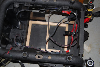
Making some progress ... I build a wooden frame so the batteries fit snug in the base. This is a H-shaped oak frame made from 3/4" wood.
It fits in the bottom box, which is an amazingly strong metal plate. It's probably 1/8" thick steel, so it's totally solid even with the weight of the two batteries. Mine are actually a bit smaller than the production batteries.
There's a simple board that spans the top of the batteries and a threaded rod between the two. A wing-nut holds it all tightly together so there's no wiggle room when it's all clamped down.
The batteries are now mounted, but I'll probably have to haul them out one last time when I put the motors and main wheels back in.
I also have the circuit breaker and auto headlight
"kill switch" mounted right below the charger power connection, so the basic circuit is coming together.
I'm working on the motor rotary encoders next.
Friday, April 23, 2010
Inch by Inch...
Small progress and no pictures this time ... tonight I mounted the on-board battery charger and sorted through the power cables. The original cables connect the batteries in series and include a 50 amp circuit breaker. I'm going to add a "kill switch" using an automotive headlight switch in the main battery feed ... this is recommended by several builders so there's a way to stop things quickly if the robot starts misbehaving.
I've been researching how rotary encoders work. I think I've settled on a design but haven't built it yet. I really should build those before mounting the motors, but I'm tempted to move ahead so I can have something running.
Hopefully I can get some time this weekend...
I've been researching how rotary encoders work. I think I've settled on a design but haven't built it yet. I really should build those before mounting the motors, but I'm tempted to move ahead so I can have something running.
Hopefully I can get some time this weekend...
Monday, April 19, 2010
First Parts Go Back Together
A small step forward tonight getting the frame back inside the garage before the rains start and putting the rear caster wheels on. They still need a better washer under the axle nut, but it's good to connect a few parts together.
I also weighed many of the parts to get a better idea what the final monster will be like.
The frame tops the scales at 70 lbs. This thing is heavy. As you can see though, it's really solid. It's made to carry around up to 300 pounds in a comfy chair.
Other heavy stuff:
- Frame : 70 lbs
- 2 large wheels : 24 lbs
- 4 small wheels : 4 lbs
- Single 12v 35 amp-hour battery, 22 lbs or 44 lbs total
- Two motors with 32:1 reduction gearbox : 25 lbs combined
- On board 24v battery charger : 5 lbs
I threw on one motor to take a look at it's mount and how it interacts with the front suspension. The two smallest wheels stick out in front and normally ride a few inches above a flat surface. These can prevent the unit from tipping forward, or help ride up a curb or small obstacle.
The front and main wheels are mounted on a small bogie bracket. This can pivot slightly from a point just in front of the center drive wheels, and is held in place by the large spring shock unit. When the front wheels hit a curb, they are pushed up, which in turn pushes down on the main wheels and thus raises the frame to a climbing angle.
Sunday, April 18, 2010
Dissecting The Wheelchair
After bringing home my wheelchair unit, I took it apart to figure out what exactly I have. Since I didn't have the whole wheelchair, it took some digging at the Pride Mobility site to come to the conclusion that I probably have a Pride Jazzy 1121. I based this on the frame style and location of the serial number.
I pulled the unit apart until it was broken down into the basic parts : main frame, motor units detached, front and rear wheels, battery charger, motor controller, plastic fairings and interconnect cables. I didn't have any batteries.
After digging around in the internet, I came to the conclusion that the motor controller didn't have simple inputs, but was interfaced to the digital joystick controller (which I don't have) with some unknown control protocol. Pride is unfortunately very tight-fisted with their service info, so I couldn't find any manuals or interface information on the web. Thus the motor controller wasn't going to be easily useful, so it went up on eBay and actually paid for a third of the wheelchair cost.
I found the Sabertooth 2x25A controller looks perfect for this application ... lots of power, and a few different control modes to play with. This seems much better than trying to hack the Jazzy controller.
The motors were dissected to remove the power brake. All electric wheelchairs apparently must have these brakes, which are engaged unless the unit is powered. I hooked them up to a power supply and found they drew about 8 watts each, so with a few bolts removed (and a big internal spring popping out) they are gone.
In playing around with my motors, I unfortunately found one gearbox was stripped. It had a weak spot where the motor would start slipping. Damn - the motors were the main component I needed. I managed to find a reasonably priced replacement on eBay, however, so a week later I was back in business.
Finally, once everything was stripped down, a few touch-ups with flat black spray cleaned it up nicely. It's now ready to start going back together.
My first goal is a basic running chassis ... two batteries feeding the Sabertooth 2x25A motor controller, hooked up with dual variable resistors for left and right motor control.
Once that's running, I'd like to add Arduino motor control, plus some sensors such as motor shaft encoders, wifi link, a camera, etc etc etc... too many ideas here!
Sunday, April 11, 2010
In The Beginning...
A couple of weeks ago I started a project that's been sitting in the back of my mind for years ... build a robot based on an electric wheelchair. The idea certainly isn't new or original, but I wanted to get my hands dirty with some hardware that can move around in the world. I want to get my kids excited too, and show them the fun of building and experimentation.
I'll use this space to track the project, and keep a record of what I'm doing in the hope it will be interesting to others tackling similar projects.
So the line is drawn in the sand, and there's a pile of parts in the garage that will hopefully become something fun and exciting... I guess I should next explain the story behind that pile of parts, and how they might fit together.
Subscribe to:
Posts (Atom)